|
|
|
|
|
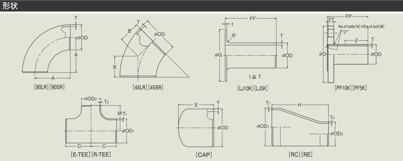
MANUAL-WELDING FITTINGS
Table D-1: Dimensions
|
Nominal
pipe size |
Long elbow
[90LR]
[45LR]
|
Short elbow
[90SR]
[45SR]
|
Lap joint JPF10K
[LJ10K]
|
Pipe flange
[PF10K]
[PF
5K]
|
JIS
10K flange
[JIS
10K FL] |
|
OD
|
A
|
B
|
A
|
B
|
FF
|
G
|
R
|
FP
|
D
|
FT
|
N
|
M
|
|
125A
|
190.5
|
78.9
|
127.0
|
52.6
|
50
|
182
|
5
|
85 |
250
|
20
|
8
|
M20
|
|
150A
|
228.6
|
94.7
|
152.4
|
63.1
|
50
|
212
|
5
|
90 |
280
|
22
|
8
|
M20
|
200A
|
304.8
|
126.2
|
203.2
|
84.2
|
65
|
262
|
5
|
90 |
330
|
22
|
12
|
M20
|
|
250A
|
381.0
|
157.8
|
254.0
|
105.2
|
65
|
324
|
5
|
100 |
400
|
24
|
12
|
M22
|
|
300A
|
457.2
|
189.4
|
304.8
|
126.2
|
65
|
368
|
5
|
120 |
445
|
24
|
16
|
M22
|
|
350A
|
533.4
|
220.9
|
355.6
|
147.3
|
75
|
413
|
5
|
120 |
490
|
26
|
16
|
M22
|
|
400A
|
609.6
|
252.5
|
406.4
|
168.3
|
75
|
475
|
5
|
120 |
560
|
28
|
16
|
M24
|
Table D-2: Dimensions
|
Nominal
pipe size
|
Equal tee
[E-TEE]
|
Cap
[CAP]
|
Nominal sizes
of
branch
pipe and smal end
|
Reducing tee
[R-TEE]
|
Cap reducer
[CAP-RC]
|
Concentric,
Eccentric reducer
[RC][RE]
|
|
OD (OD1)
|
C=M
|
E
|
OD2
|
C
|
M
|
Q
|
H
|
|
125A
|
123.8 |
76.2 |
|
|
|
|
127.0 |
|
150A
|
142.9 |
88.9 |
125A
|
142.9 |
136.5 |
(170) |
139.7 |
200A
|
177.8 |
101.6 |
125A
|
177.8 |
161.9 |
(180) |
152.4 |
|
150A
|
168.3 |
|
250A
|
215.9 |
127.0 |
125A
|
215.9 |
190.5 |
210 |
177.8 |
|
150A
|
193.7 |
|
200A
|
203.2 |
|
|
300A
|
254.0 |
152.4 |
125A
|
254.0 |
215.9 |
240 |
203.2 |
|
150A
|
219.1 |
|
200A
|
228.6 |
|
|
250A
|
241.3 |
|
350A
|
279.4 |
165.1 |
150A
|
279.4
|
238.1 |
250 |
330.2 |
|
200A
|
247.7 |
270 |
|
250A
|
257.2 |
|
|
300A
|
269.9 |
|
400A
|
304.8 |
177.8 |
150A
|
304.8 |
263.5 |
260 |
355.6 |
|
200A
|
273.1 |
280 |
|
250A
|
282.6 |
|
|
300A
|
295.3 |
|
350A
|
304.8 |
|
|
|
|
|
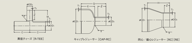
Manual welding of large diameter side
Automatic welding of branch pipe/small diameter sides (with straight length
end) Fittings
Table D-3: Dimensions
|
Nominal
pipe size
|
Nominal sizes
of
branch
pipe and small end
|
Reducing tee
[R-TEE] |
Cap reducer
[CAP-RC]
|
Concentric,
Eccentric reducer
[RC][RE]
|
|
OD (OD1)
|
OD2
|
C
|
M |
Q
|
H
|
125A
Bevel end at mother pipe side |
50A |
120 |
130 |
140 |
190 |
| 100A, 80A, 65A |
140 |
140 |
- |
150A
Bevel end at mother pipe side |
100A, 80A |
150 |
160 |
- |
205 |
| 125A |
170 |
170 |
- |
200A
Bevel end at mother pipe side |
100A |
160 |
180 |
170 |
220 |
| 150A, 125A |
180 |
190 |
- |
| 250A |
8A,
1/2", 3/8", 1/4" |
110 |
180 |
170 |
|
| 25A, 20A, 15A, 10A, 1", 3/4" |
130 |
190 |
180 |
| 50A, 40A, 32A |
150 |
200 |
190 |
| 100A, 80A, 65A |
170 |
210 |
200 |
| 150A, 125A |
190 |
220 |
210 |
250 |
| 200A |
210 |
240 |
|
270 |
| 300A |
8A,
1/2", 3/8", 1/4" |
120 |
200 |
200 |
|
| 25A, 20A, 15A, 10A, 1", 3/4" |
140 |
210 |
210 |
| 50A, 40A, 32A |
160 |
220 |
220 |
| 100A, 80A, 65A |
180 |
230 |
230 |
| 150A, 125A |
200 |
240 |
240 |
280 |
| 200A |
220 |
260 |
|
300 |
| 350A |
8A,
1/2", 3/8", 1/4" |
130 |
220 |
210 |
|
| 25A, 20A, 15A, 10A, 1", 3/4" |
150 |
230 |
220 |
| 50A, 40A, 32A |
170 |
240 |
230 |
| 100A, 80A, 65A |
190 |
250 |
240 |
| 150A, 125A |
210 |
260 |
250 |
410(150A) |
| 200A |
230 |
280 |
270 |
430 |
| 400A |
8A,
1/2", 3/8", 1/4" |
130 |
250 |
220 |
|
| 25A, 20A, 15A, 10A, 1", 3/4" |
150 |
260 |
230 |
| 50A, 40A, 32A |
170 |
270 |
240 |
| 100A, 80A, 65A |
200 |
280 |
250 |
| 150A, 125A |
220 |
290 |
260 |
| 200A |
240 |
310 |
280 |
460 |
|
|
Please refer to common dimensions pages for
outside diameter (OD), thickness (T) and length (ℓ) of straight end length.
Manual-welding fittings below 100A and
from 350A to 900A are available. Please contact us.
Manual-welding elbows, reducers, caps and
tees are JIS B2312, 2313 specification products, and lap joints are JPF SP001
specification products, and flanges are JIS B2220 specification products. Their
dimensional tolerance is determined by the dimensional tolerance of
respectively applicable standard.
|
|
|
|